Getting an analog signal out of a component and into a waveguide for high isolation routing is not so simple as placing a microstrip or stripline coming off your source component. Here I use MACLIN3 Microstrip 3-Conductor Asymmetric Coupled Lines in Keysight ADS.

A Designer S Guide To Microstrip Line
A coplanar wave guide.

. A Practical Guide to the Design of Microstrip Antenna Arrays. Here I confirmed Coupled line model in Cadence Spectre by simple balun. Provides information on how to design Microstrip Line with many feeds and have even given details about Patch Antenna by comparing various other feed types.
Creating the Microstrip Repeat the previous steps to create 7 more variables with the following values. Hope it would be useful. A Designers guide to Microstrip Line - Free download as PDF File pdf or read online for free.
Your signal is drive by a PCB net on top with two ground plane area. PCB material and air. It is routed on the PCB surface and surrounded by two environments.
Designers Guide to Microstrip Line. Engelmann from the Federal Telecommunications Laboratories of ITT presented as a competing printed circuit line. Of these more than 60 million electronic full texts can be accessed directly.
Attenuation of TE11 mode in a circular guide. The Designers Guide Community Forum - ADS to design and simulate antena please help me The Designers Guide Community Forum - Problem with ADS MCLIN. Technol kanpur-208016 india source microwaves.
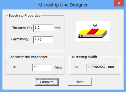
To design a 50Ω microstrip line enter these values into the designer dialog and set Z0 50. 11 Overview of Microstrip Antennas. They are generally economical to pro-.
H W W H Z eff O ln 8 025 60 ε 33 H W 1. 1. Beyond 60 GHz its application is restricted due to the losses in the line.
The model assumes a Quasi-TEM mode of propagation and incorporates the effects of dielectric and conductive losses. The first Microstrip developments were done shortly after the appearance of Barretts article in 1952 by DD. H W 1.
Trvedi A Designers Guide to Microstrip Line Microwaves May. Patterns are somewhat hemispherical with a moderate directivity about 6-8 dB is typical. Because of the symmetry unbalance in Microstrip all discontinuity elements possess.
Microstrip consists of a strip conductor land on a dielectric substrate backed by a ground plane that radiates when the spacing between the ground. Easy to use in an array to increase the directivity. For example a 2 inch microstrip line over an Er 40 dielectric would have a delay of about 270 ps.
A Designers Guide to Microstrip Line Microwaves p. Trivedi A Designers Guide to Microstrip Line Microwaves p. There are over 130 million records that can be searched in the TIB Portal.
A microstrip antenna array is one of the simplest forms of antennas available. In general the microstrip line is used to conduct the electromagnetic wave at low frequency. Substrate_W 1000 mil Substrate_H 60 mil Gnd_H 4 mil Trace_W 1147mil Trace_H 4 mil Waveport_W 419 mil Waveport_H 115 mil Using these variables we will define a 100x100 board with a 60.
A designers guide to microstrip line. In this video a 50 Ω microstrip line is designed and its step by step process is explained. A microstrip line.
In this study we designed and analyzed five terahertz microstrip patch antennae based on a modified photonic band gap substrate in the frequency range from 05. For this project you will use an FR-4 substrate of thickness h 12mm relative permittivity er 45 and loss tangent tand 002. However dependecy of substrate thickness is fairly different from Keysight ADS result.
Microwave and mmWave Computer. I think Keysight ADS result is reasonable. DESIGN FEATURE Microstrip Lines P RINTED transmission lines are widely used and for good reasonThey are broadband in frequency.
Our main discussion of microstrip dispersion is now here. Trivedi A Designers Guide to Microstrip Line Microwaves May 1977 pp. With εeff calculated in 51 or 52 above the characteristic impedance of a Microstrip line can be calculated as follows.
Lxxc0fin here c0 299792e008 ms the speed of light is reserved word in ADS. This circuit component models a length of Microstrip Transmission Line. Easy to feed coaxial cable microstrip line etc.
Fundamental balun operation itself is no problem. Designers Guide to Stripline Circuits Supplement B. Here if you set frequency as fin1GHz.
Introduction to planar transmission lines. They provide circuits that are compact and light in weight. The microstrip line is a planar transmission line that is used prominently in RF and microwave circuits.
This document is rarely available and obtained after a great effort. Instead you need to create a special microstrip to. 3 Run S-parameter simulation with sweeping microstrip length.
Terminate the transmission line in its characteristic impedance when the one-way propagation delay of the PCB track is equal to or greater than one-half the applied signal risefall time whichever edge is faster. Due to this there is a general consideration that the use of microstrip transmission line at THz frequency is impractical. Basically you have a net on the top driving the signal and a ground plane on the PCB bottom.
Can any one post the following paper. Microstrip transmission lines can guide high-frequency designers in the proper application of this venerable circuit technology. Design a 50 ohm impedance microstrip line for RF signals.
A Designers Guide To Microstrip Line Equations data and conclusions from many sources are compiled to define transmission characteristics. The antenna consists of a single printed circuit board with an RF connector and perhaps an absorptive load. Discussions center on loss circuit Q dispersion dimensional ratios and moding.
The link for the online calculator used is httpswwwemtalkc. 444 120 H W H W Z eff O ε π 34 2 I. There are two ways to design your emitter to antenna solution.
Attenuation of TM modes in circular guides. At the top of Device Managers Tools Menu find Microstrip Designer and open it. 3 method c are gene of papers appeared form exp and com The cl reported Wheeler for Wh microstr reported work.
RF structures can be complicated to design and layout particularly because many RF systems lead double lives as digital systems. Go to our book section and buy a book on microstrip. Trivedi dk indian inst.
Easy to incorporate with other microstrip circuit elements and integrate into systems.

Microstrip Line Design And Simulation In Ads Youtube

A Designer S Guide To Microstrip Line Pdf Document
A Designer S Guide To Microstrip Line Pdf Document

Pdf Reviewing The Basics Of Microstrip Lines An Understanding Of The Fundamentals Ofmicrostrip Transmission Lines Can Guide High Frequency Designers In The Proper Application Of This Venerable Circuit Technology Semantic Scholar
Rf Tutorial Lesson 4 Analyzing Microstrip Lines Discontinuities Emagtech Wiki
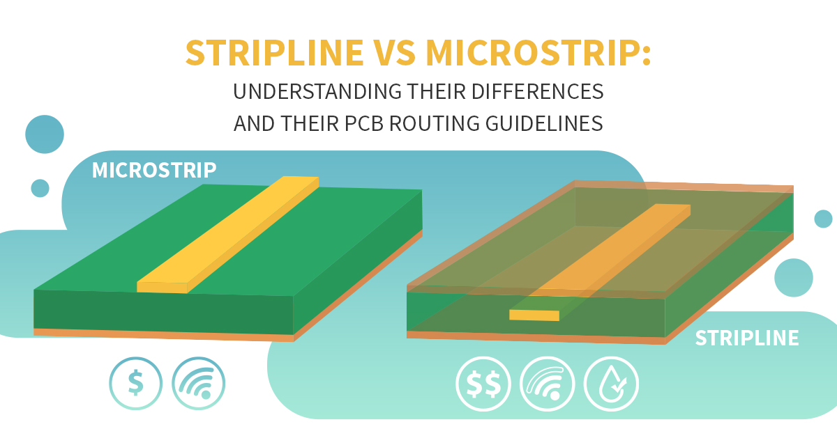
Stripline Vs Microstrip Pcb Routing Differences And Guidelines Pcb Routing

A Designer S Guide To Microstrip Line Pdf Document

A Designer S Guide To Microstrip Line Pdf Document
0 comments
Post a Comment